Well this was a disaster; engine failure on lap 1.
Well this was a disaster; engine failure on lap 1.
My third year of running a FF1600 and it’s my 3rd Mondiale! I’ve just been off to Ireland to test the new car. It’s good or will be with a few little things ironed out. I was testing and racing at Kirkistown. It’s another world over there compared to the mainland UK. Very easy going and the track is a lot like an old style track where it’s all about the racing with no fancy paddock. I met some really intesting characters over there and learned a lot about Mondiale the company.

Sadly for Mondiale and Leslie Drysdale (the designer who previously designed Crossles), car building ended in the early 90s when the company turned to general engineering work to keep going and beat the recession. They built a large number of different cars for the American market which was their biggest. There was also a surprising parallel with the demise of an earlier Northern Ireland car building company you may just have heard of called DeLorean in that one of the directors, Colin Lees turned to drug money to pay his debts! A quick Google of the name Colin Lees turns up quite a few interesting stories. This rather ruined the reputation of the company and I got the impression this made Leslie want to turn his back on building cars and concentrate on other things to bring in the cash.
The engineering company continues to this day but they don’t build cars. There was a new car partially built for 93/94 but Leslie refused to finish it. There are still people all these years later hoping they can peruade Leslie to finish it off the way he wanted as it was a nice design from the looks of it with pull-rod rear suspension as well as pull-rod front suspension. About the only thing besides the driver which can be located low down to keep the centre of gravity low is the suspension. The engine position is fixed and a chassis has to be as safe and as rigid as the next one. This car had both front and rear suspension mounted horizontally very low on the floor which reduces the weight transfer in a corner and allows the inside tyres to do more of the work and not overload the outer tyres. Additionally pull rods can be lighter than push rods as they operate in tension and not compression.
Beyond the talk of cars I found the guys who race at Kirkistown have a very lively social scene! After testing much beer is consumed well into the night and even the next day. The restaurant and bar at the track is buzzing throughout the night and often features live music. Not the greatest race prep but it doesn’t seem to slow the guys down very much; these guys are quick! I have to thank Hugh Reid in particular for making me feel very welcome during the weekend.
On track the conditions were poor but the car set up by John Harris handled beautifully. It was so placid I did not make the most of it given my recent experience of Mondiales set up by the less skillful spanner, me! Where my other cars would bite this was forgiving. The only issue I had to live with was a seized up spherical bearing which was taking away any feel from the steering. The car has not been used in 20 years so this kind of issue was to be expected. The American Loynings engine, rebuilt by Scholar, is a bit of a stonker although I nearly managed to blow it up already when the gear linkage broke and I got 1st instead of 3rd. This cut short my qualifying session which were my only dry laps. Given it was very wet and for me the race was just testing (I couldn’t score points or win a trophy having not filled in a tyre sheet) I just allowed a gap to develop to the quick boys up front through the dauting Debtors Dip corner knowing I could pick them back up through the rest of the lap. It has decent pace that car. I look forward to seeing what it can do when driven in anger!
Since the hasty rebuild of our Mondiale M89s back in April the car has never really been easy to drive. A few people have remarked how entertaining it was to watch but that’s not fast and it’s not why we go racing. And you know, going sideways gets a little boring after a while. At least it’s not understeer.
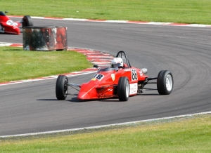
So, we’ve worked on ways of improving the handling balance over the last few rounds and it’s got better but it’s still on the oversteery side. In fact during testing for the last round at Oulton Park the car was almost perfect with a knackered 4 year old front left tyre and three newish tyres. New tyres all round just ruined it. Anyway we’ve got it sussed now but before I explain what we’ve you may wish to read the following post to understand how suspension affects the balance of a chassis…
https://firmtec.wordpress.com/2015/07/11/how-suspension-changes-the-handling-balance-of-a-car/
To summarise, we found the higher the weight pushing down on a tyre, proportionally it’s grip level is reduced. That is to say it will grip more when pressed down harder because it’s being pushed down harder but with a lighter load the ratio of grip to weight pressing it down will be higher.

We also concluded the end which can roll more will have more grip. The more we stiffen one end the less it rolls when cornering. The stiff end of the car will transfer weight to the outside tyre more than the soft end when cornering. This would mean the outside tyre on the stiff axle would have more weight on it than the outside on the soft end. This soft end therefore will have more grip on it’s outside tyre as it is more lightly loaded and the whole axle will have more grip.
To summarise the summary; the end with the most roll is the end with the most grip!

We have too much oversteer so we need to allow the rear end to roll more and reduce the amount the front end can roll. First thing we do is look at the rear anti-roll bar and obviously we need less of it!
The roll bar effectively tries to twist the chassis back to a non-rolled position when one wheel is displaced upwards opposing roll. On the rear of the Mondiale we have two blade type roll bars. We set them both to the most bendy softest position – 90 degrees to the link pushing them upwards. This is unusual in that one of them is normally fixed in the stiffest position but we still had too much oversteer so we tried both (the guys in Ireland run both these full stiff).
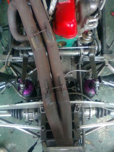
This helped improve the car after qualifying at Donnington but it was not enough so next we tried to stiffen the front anti-roll bar.
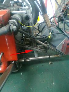
The higher the link is up the front anti-roll bar the more stiff it appears to the car. This is because, the closer links are to the axis the bar rotates around, the less leverage the suspension has on it so more force is required for the same amount of displacement of the roll bar. We had this as far up as the link would go! This is already a thick, stiff bar. At least in the second race at Donnington the car became a little more driveable like this but it was way too oversteery!
We looked at using a different hole in the upright for the rear suspension which would give a lower roll centre but this limited the rear droop which was already a bit skinny and causing oversteer problems of it’s own. So we really had to look at the spring rates next.
Originally this car came with 400lbs springs front and rear. We had a slight issue of the car bottoming out at the rear so we fitted the 425lbs springs to the rear to avoid this (you don’t want a FF1600 hitting the floor it damages the engine).
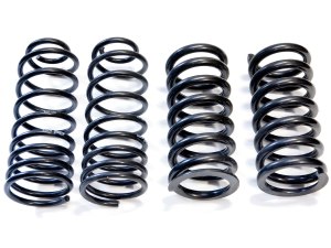
A stiffer spring feels good to the driver as the car becomes more responsive to the brakes and steering. However if you keep going stiffer, it eventually starts crashing over bumps and kerbs and effectively just reduces the grip on the road due to the time the wheels are airborne! As someone who regularly rides over 200 miles a week on a bicycle I know all about this! You tune a bicycle’s handling with just tyre pressures (particularly in the wet). You always want more front grip than rear grip so I run my bike tyres at about 5-6bar front and 8-9bar rear. If you’re riding over some bumpy road it will be the rear which crashes around and slides first!
So to reduce the oversteer we could have gone softer on the rear (not really an option due to the bottoming over bumps) or stiffer on the front. I had some 450lbs springs. This gave a very high frequency wheel rate but it felt about right given the balance we had. I first tested the car at Oulton Park after fitting these and sure enough it felt a lot better and equally pleasing was the fact the front still ran over the kerbs fairly well. Also, given the chicanes they have there is was useful to have a stiff car in roll as less time is wasted changing direction.
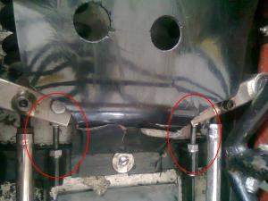
We also tried running zero droop with a slight preload – a slightly heavier person sat in the car when we set the droop stops. Running zero droop front suspension means when the car corners the inside wheel cannot move downwards and take the weight of the inside of the car putting more load on the inside rear wheel and outside front wheel. This sounds like just what we need especially when accelerating when the front wheels would experience droop. It did help traction but still mid-corner it was all about oversteer.
The problem now was we still had too much oversteer and no more scope for adjustment anywhere – this would not have been ideal in the wet. The final tactic was to reduce the rear ride height to the legal limit so the car ran level instead of with a little rake (this lowers the roll centre height). Again this helped and for the first time the car felt good in the next test session at Oulton running in a respectable low 1m51s times on old tyres. But still there was too much oversteer around corners like Druids where the car was sometimes going through the entire corner on opposite lock. With new tyres it reverted back to being slow.
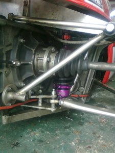
Last year the car had a bit of understeer sometimes without having to resort to these extremes. That could have come from the semi-seized front rockers we had but I don’t think so. The difference was subtle. I reassembled the lower wishbones in such a way as to increase camber gain by fitting the spacers the other way around. This meant the lower wishbone would flatten out in roll making it longer and pushing the rear wheel outwards at the bottom. Unfortunately I’d forgotten all about this and it happens to moves the rear roll centre upwards considerbly!
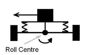
The roll centre is the point around which the chassis rotates. It’s obvious in the picture above where that is but with wishbone suspension you have to draw it. Firstly though why is it important?
Before we begin the amount the chassis rolls is related to the roll centre but the weight transferred from inside wheels to outside wheels in total is not affected by the RC – this is purely down to the position of the CoG and the cornering force.
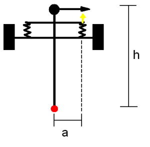
As the distance h is so large the leverage the cornering force at the centre of gravity has on the chassis about the roll centre is very large compared to the leverage the spring has on the chassis through the distance ‘a’.
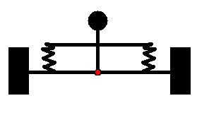
Now compare that to the leverage the cornering force has on a much higher roll centre as above. With the same springs and weight, the axle with the lower roll centre would roll considerably more given all of the leverage the cornering force has on the chassis through the roll centre. If we had the low roll centre at one end and the higher roll centre at the other what would happen? Well the chassis can only rotate through one angle as it is rigid (well should be compared to the stiffness of a spring!). That means the low roll centre end would still be rotating further at the angle the high roll centre end side would have reached equilibrium. So the high roll centre end starts taking some of the load from the low roll centre end increasing the load on the high roll centre end’s outside tyre and reducing it’s grip. Obviously this reduces the load on the high roll centre end’s inside tyre as we know the total load on the axle is fixed by the position of the CoG.
Again we could have simply reached this conclusion from the basic principle ‘the end which rolls more has more grip’. Obviously the end with the low roll centre will roll more with all that leverage.

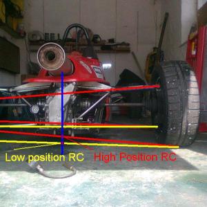
In the above picture we can see with the spacer in the lower position the angle of the lower wishbone has it pointing upward and this gives a much higher RC than if we put it above the wishbone joint (the yellow lines). It could be about 2″ lower in this position. Remember this will cause more rear roll and hence will give more rear grip. For reference the front RC is on the floor or lower depending on ride height.
The small change we made to the placement of the spacer really made a difference to the roll centre height – far more that a ride height change could make. We could get this even lower by using the low hole in the upright but as mentioned this will limit rear droop which is already insufficient.
The handling as it was on Oulton was just on the outside of the tuning window. So, with the rear roll centre much lower we expect the handling to be much more tunable with a understeer/oversteer balance being able to be achieved within the range of the rear bar.
If this isn’t the case there must be a crack in the chassis allowing it to flex. Anyway before we next run it it’ll need a new engine and will have to be put back together!
Michael
You may have heard stiffening the rear suspension of a car causes more oversteer and vice verse but why?
Lets go right back to fundamentals. Imagine a 100kg car with the weight in the middle of all four wheels. Imagine this car cornering in such a way it just generates 1g of lateral acceleration. Each axle must generate 50kg each to react the centripetal force. If the weight of the car doubles to 200kg the force per axle is now 100kg each. If the tyres can produce about the same grip in lateral force as the weight pushing down on them, they can generate this 1g of acceleration. We could say this tyre has a co-efficient of friction of 1.0 which means the friction force divided by the weight is 1:
coefficient of friction (mu) µ = Friction Force / Weight or
µ = Lateral Force / Normal Force (normal is weight pushing down)
If we move the weight rearwards so that the rear tyres now have 150kg on them and the fronts only 50kg, the rear tyres now have to produce 150kg of lateral for the same acceleration but, as they have proportionally more weight on them and they produce the same amount of grip as force pushing down on them, that’s fine, they can cope. The point is, putting more weight on one end of the car requires a larger lateral force to be generated by the tyres but it also gives the tyres a larger vertical load to create that force with. However in this case, under steady state cornering, most tyres which were just on the limit with the weight in the middle would lead to the heavy end starting to slide. That’s because tyres do not grip prortionally as well when a large load is placed on them as compared to when a lighter load is pushing them into the road. They begin to saturate.

If we look at some real tyre data we can see the coefficient of friction for a rear ACB10 (the Formula Ford 1600 tyre) is higher with 84kg (the blue line) pressing down on it than when 306kg (the orange line) is pressing on it… considerably so too! These are quite useful data to have as the weight of the rear of a FF1600 is about 300kg and the typical load on the inside tyre, when cornering fast, is about 80kg. We’re only really interested in the ultimate value at about 9 degree of slip angle where the tyre begins to stall and can longer produce more lateral force despite any increase in slip angle. Obviously the tyre creates a larger force at 300kg but proportionally for the weight pressing down on it, it is less.
What we want to achieve handling-wise is a car which slides a similar amount front and rear (if anything a touch more sliding at the rear but it’s up to the driver to control this with his right foot). That means we need the coefficient of friction of the tyres to be about the same front and rear. We know now that if we put a larger weight on one end of the car, the tyre will have a lower coefficient of friction at that end and will slide more. So the only way around this is to use a fatter tyre at the heavy end which will saturate at a higher load.
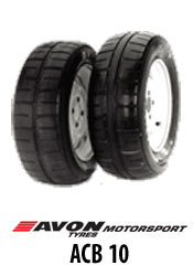
As the rear of a FF1600 is about 300kg and the front 200kg we use a wider tyre at the rear which will give a higher coefficient of friction at 300kg than the narrower front tyre – it’s about 1.3 compared to 1.2 for the narrower tyre at 9 degrees of slip angle. If you had the front tyre on both ends you’d get loads of oversteer as the rear is heavy. The side force created by all of this weight would not be able to be reacted as well by the rear tyres despite the larger weight pressing them down just because the tyre would saturate earlier. The wider tyre on the rear should give a FF1600 a reasonable balance before we start to tune it but a precision weapon like a FF1600 race car needs tuning and here’s how we do it…
We really don’t need to do any maths to understand this but we need to look at a basic diagram and have a think how we would calculate the forces on all the tyres.
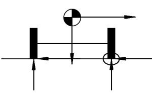
The centre of gravity creates a force pushing the chassis down and also pushing the chassis sideways when cornering. You would calculate all of the forces by working out all of the moments about a point like the circle around the bottom of the wheel. But what is important is that we understand the total forces that point < that way equal the total forces pointing > that way and the same up and down. The force pushing up on the tyres by the road is the same as the weight of the car. The side force from the chassis is the same as the total side force created by BOTH tyres. Because the centre of gravity (I’ll now call it ‘the weight’ for simplicity) is above the ground it has a tendency to lift the inside tyre off the ground as the car rotates about the circle. The thing keeping it on the ground is the weight pushing it down rotating it the other way about that circle.

A real car obviously has two axles not just the one shown in the diagram. The proportion of the total weight of the car on the front and rear axles is fixed by the location of the centre of gravity and nothing else (apart from forwards acceleration)!
We know the inside tyres have less weight on them compared with the outside tyres when you go around a corner, however, the total weight on the axle (i.e. the front inside and front outside tyres for example) never changes. The front axle carries the same weight whether you’re going in a straight line or cornering that hard you’re on two wheels. The only thing that can move weight from the front to the rear is accelerating/decelerating (roll bars can’t do this despite what idiots say!).
The cornering force increases the load on the outside tyres and decreases the load on the inside tyres. Even though the total weight on an axle never changes we can change the proportion of weight on an axle’s inside tyre compared with the outside tyre on a car with suspension. Imagine this…

Above is a car with a springy hinge one end and a rigid frame mounting the wheels at the other. We know the total weight on each axle is fixed by the position of the centre of gravity and does not change. However, imagine it cornering with enough cornering force causing the car to roll. The inside wheel of the rigid end would instantly come off the ground as it’s so stiff whereas the end which can rotate will stay on the ground (unless it’s that fast it tips the whole car up – lets assume not!). The whole inside of the car still weighs something and this load has to be carried by the inside tyre on the end which is free to rotate – the rigid end has no load on the inside because it’s rigid and any roll causes it to lift clear off the ground. We know the total weight on the rigid end’s outside tyre must therefore be the total weight of the axle whereas the total weight of the hinged axle will be shared between the inside and outside tyres.
Now let’s say all four corners have the same tyre and the centre of gravity is bang in the middle of all 4 tyres like earlier. Say each tyre has 25kg on it. Up to now we’d say both axles would slide the same amount when going around a corner because the weight is equally shared, however, now we have a different situation. Because of our basic suspension system we’ve invented, one tyre, the outside tyre on the rigid end has all of the weight of that axle on it (50kg) and the other could have almost the same weight on both the inside and outside tyre depending on how springy we make the hinge, position of CoG etc… It doesn’t matter, what is important is that on the hinged (or soft) end the axle weight is shared between the inside and outside tyres and on the rigid (stiff) end the weight is all on the outside tyre.
To calculate the grip each axle has we need to know the coefficient of friction of the tyres on each axle. What we do know is the tyre with the lowest coefficient of friction will be the tyre which is carries the entire weight of that axle on it’s own (the rigid axle’s outside tyre). The next lowest will be the softer, hinged axle’s outside tyre followed by the hinged axle’s inside tyre. The friction force from the rigid axle will be less than the other hinged/softer axle because the coefficient of friction of these wheels will be higher.
Because we’ve introduced a suspension system to the car which allows the chassis to roll we’ve created a situation where one axle can have more grip than the other because it can roll more than the other end. The extreme case is where one end is completely rigid and the other end hinged but the principal applies to a stiffly sprung end and a softly sprung end. One thing that is important is that the whole chassis which connects the ends together is very rigid so the angle each end rolls through is about the same! If not the weight on the inside wheels may not be controlled by the other end so much.
We can make one axle stiffer than the other in the following ways:
These will be discussed in seperate posts!
Michael
The minimum weight of the Formula Ford Race Car without the driver is 420kg. The minimum weight with the driver is 500kg but the driver is only ~60kg so we need to find almost 20kg! Actually the car is slightly heavy so it’s about 15kg.
To keep the centre of gravity as low as possible this weight must be placed right on the floor but there isn’t a great deal you can secure a lead weight to that low so we had to make our own ballast to fit within the chassis rails. This is the safest and most effective way of adding ballast. It was just a bit dangerous. Ooo Ayy!
We melted the lead into a mold effectively casting it within a wooden frame. On reflection this was a reasonable idea but using a large tray was a bad idea. It made it difficult to handle and also lost heat too quickly through that large surface area. In future a small pan would be better.
After our eventful race last weekend I looked under the car which had bottomed out and realised we’d better check that engine!
Exposed flywheel with scuffs
The flywheel on these engines can hit the floor which can put a crack in the crankshaft around the rear main bearing. I’ve had two engines with crack here. One blew up in Anglesey and the other was condemned in an engine builder’s workshop as being close to the big bang.
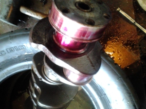

We want this engine back in the other car by the end of the week so we tipped it on some tyres and got the crack out quickly. Armed with some Ambersil Leak and Flaw detector (http://uk.rs-online.com/web/p/leak-flaw-detector-sprays/4955027/) we sprayed the centre main bearing and the area of the crankshaft which is subject to cracking. I was keen on spraying the main bearing as the previous engine had a crack in it here. Since I first drove the car with this engine it had low oil pressure (35psi on the straights) so I suspected this engine had the same problem.
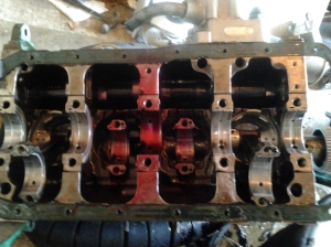
I hate being right sometimes… the centre main bearing shell gave it away (as did the oil pressure) before we even got the spray on. It was badly worn and yes there is a crack here. Luckily, well sort of, the crank is fine but is scuffed a bit.
NDT Spray showing crack in centre main bearing
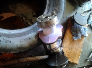
That’s it for this block really. I need an engine in the car by the end of the week so I put it back together. The way the engine builder (believed to be Stevie Patton) sets the cam timing is to put an undersized dowel in the camshaft drive and use the bolts like a vernier. We tried to mark the position but I think we lost it so it’s also likely to be down on power now too! All round a bit of a rubbish day but it made it easy to decide on what to do next. Sell the 88 cheap and buy a brand new, crack free engine. I never liked that car anyway!

Following on from building the car in a few evenings some problems we faced re-occurred to make this round more of a test session than a race. Michael qualified 6th out of 19 after 10 laps which was not bad considering the car had a major handling issue and we hadn’t tested the car until that session. Unfortunately the clutch failed in qualifying and we did not get this fixed for race 1. Race 2 we started right at the back but with a hampered car Michael failed to make progress.
The main issue with the car which we could not address was the lack of rear droop. The speed at which the car was re-assembled meant we had to assume the spare dampers fitted. Sadly they did not allow for any droop in the rear suspension which badly affected traction out of corners.
A weekend that promised so much and delivered so little mainly due to Michael screwing it up! A flat new tyre did not help leading to guessing a setup.
In the video we see a confession (sorry George)
A botched up crash repair job.
And speculation as to why a smashed up race car was faster than the one painstakingly setup by someone not very good at painstakingly setting up a race car!